

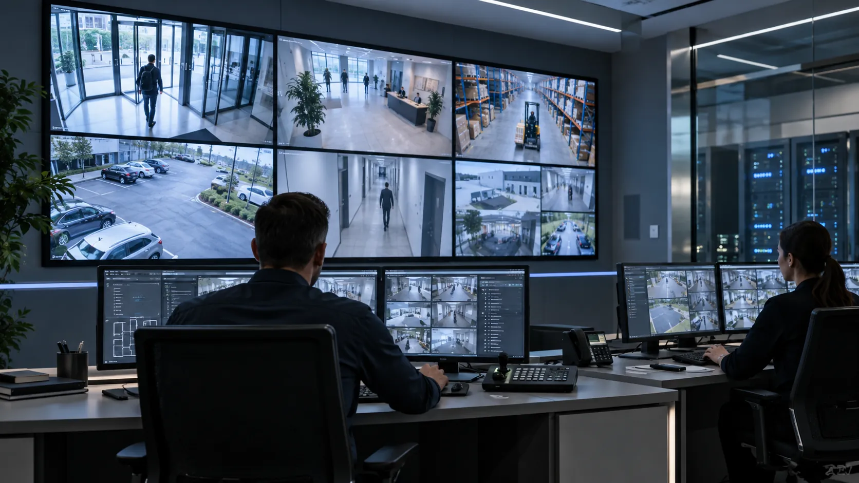
A video surveillance system is a chain of functions that turns activity in a scene into video that can be viewed live, recorded, stored, searched, and played back later. Cameras are the visible part of that chain, but the system also depends on video encoding, transmission, recording services, storage, management software, and operator access.
That system view matters because a camera can capture a useful image while another layer prevents the video from reaching an operator or being available later. Modern IP architectures make these relationships especially clear: cameras behave as networked video devices, software clients request and manage streams, recording systems preserve selected video, and storage holds the resulting data.
The system is a set of connected layers
The exact products and topology vary, but most video surveillance systems can be understood as four functional layers:
- Capture and encoding: cameras create video and encode it into a digital stream.
- Transmission: a network or other transport path carries video, control traffic, and—where supported—events or metadata.
- Recording and storage: recording services decide what video is written, while storage provides the media and capacity that retain it.
- Management and use: video management software (VMS) and client applications can provide live viewing, playback, search, configuration, permissions, and event handling, depending on the implementation and supported capabilities.
Those layers can be combined in one appliance, distributed across multiple servers, partly located at the edge, or delivered through remote services. The functional relationships remain useful even when the physical architecture changes.
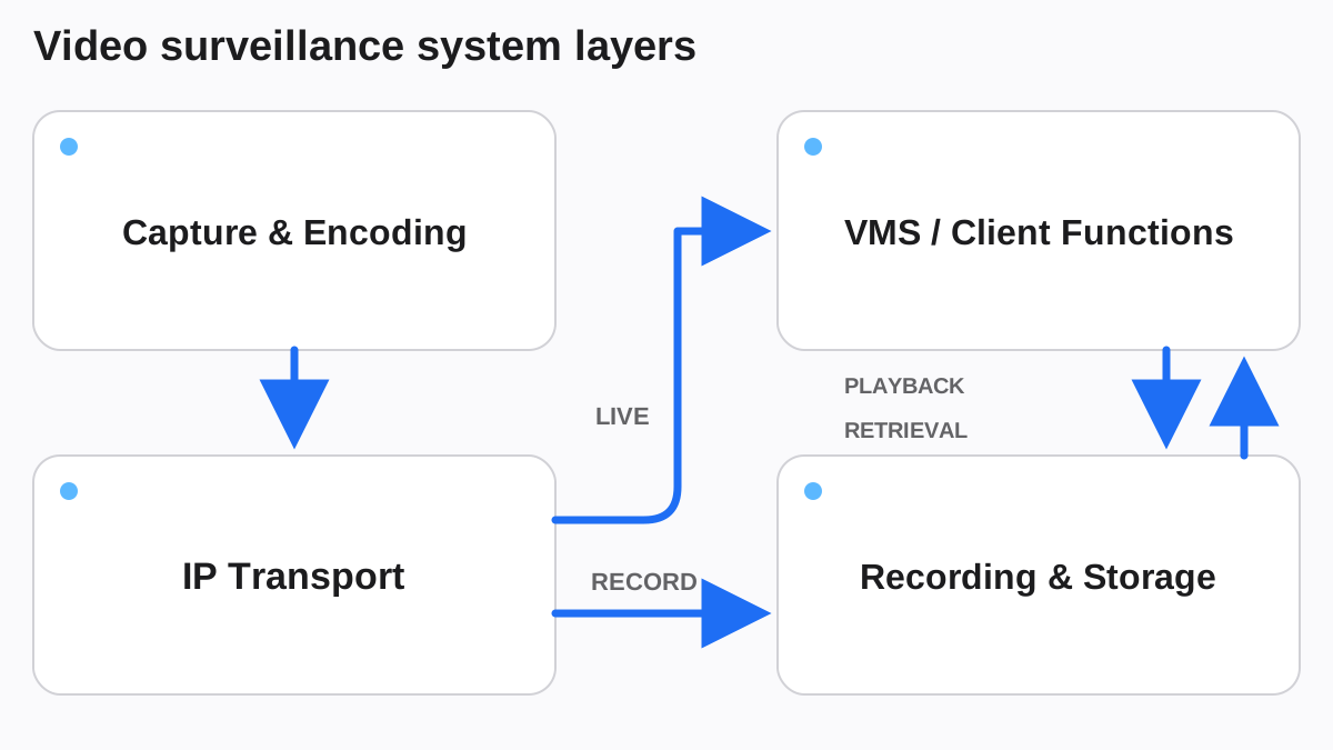
The diagram shows the core flow rather than a prescribed topology. Real systems may add redundant paths, analytics, access-control integrations, remote sites, or cloud services, but those additions still depend on the same basic chain.
Cameras capture and encode the video
At the edge of the system, a camera turns a scene into a video stream that another component can transport, display, or record. In an IP system, that camera is also a network-connected computing device. It exposes services for configuration and video delivery and may also produce audio, events, or metadata when those functions are supported.
Video is normally encoded before it is transmitted and stored. Encoding reduces the amount of data compared with an uncompressed video signal and creates a stream that other system components can process. Current ONVIF Profile T systems can support H.264 and H.265 video encoding as part of standardized IP video streaming interfaces.
The camera layer therefore does more than “take pictures.” It is the point where image capture becomes a managed video stream.
Detailed choices about field of view, lens selection, mounting position, and scene coverage are separate design questions. They determine whether the captured scene is useful, but they are not the subject of this system-foundation article.
Transmission connects the camera to the rest of the system
Once video has been encoded, it must reach the components that need it. In a networked system, the IP network provides that transport path between cameras, recording services, management servers, and viewing clients.
A single camera stream may be requested by more than one function. A recorder may receive video for storage while an operator client requests live video, and another service may consume events or metadata. How that traffic is distributed depends on the implementation, so a surveillance network should not be treated as a passive cable between a camera and a recorder.
ONVIF Profile T defines standardized interfaces for advanced IP video streaming between conformant devices and clients. The value of an interface standard is interoperability: a device and a client can share an agreed method for requesting and controlling supported functions instead of relying only on a proprietary relationship.
Transmission is also a dependency. If a design relies on centralized recording and the required network path is unavailable, video from that path may not reach the recorder while the interruption exists. Architectures that use supported on-device recording can create a different failure behavior because some video can be recorded at the edge.
Recording and storage are different functions
Recording and storage are often discussed together, but they solve different problems.
Recording is the process that determines what video is written and how it is organized for later use. A recording service determines which incoming video is written and organizes it so that the system can retrieve the relevant material later.
Storage is where the recorded data resides. Depending on the architecture, that may be local media in a camera, storage attached to a recorder or server, shared network storage, or a remote service. The choice changes the system’s dependencies and operational model; it does not change the basic need to preserve video in a form that can be retrieved.
ONVIF Profile G reflects this distinction by covering recording, storage, search, retrieval, and playback functions for conformant IP video devices and clients. It also recognizes that recording can occur over the network or on the device itself.
No universal retention period or storage capacity can be inferred from the system type alone. Those values depend on the actual recording policy, video characteristics, operational needs, and any applicable organizational or legal requirements.
Video management software coordinates the system
Video management software (VMS) is the operational layer that brings the other components together for users. It can provide a common interface for camera configuration, live viewing, recorded playback, search, event handling, and user permissions. In larger architectures, management and recording functions may be split across multiple services rather than running on one machine.
The VMS is not the video itself and it is not necessarily the place where video is stored. Its role is to coordinate supported devices and services and present those functions in a usable operational model.
This distinction becomes important when troubleshooting. A user who cannot see live video may be dealing with a camera, network, service, permission, or client problem. A user who can see live video but cannot retrieve yesterday’s recording is dealing with a different path through the system. Treating both symptoms as a “camera problem” hides the layer that actually failed.
Live monitoring and recorded playback are separate workflows
Live monitoring asks the system for video that is being produced now. The path is typically camera → transmission → client or management service, with the exact routing determined by the architecture.
Recorded playback asks for video that has already been written. The path is typically client → management/recording service → storage → client. The camera may no longer be involved in delivering the stored video.
That difference explains why one workflow can remain available while the other fails. A live stream can be healthy even when recording has stopped, and a stored recording can remain playable even when a camera is currently offline.
For operators and maintainers, the useful question is therefore not simply “Is the camera working?” It is “Which system path is working, and which path is not?”
Metadata and events can travel with the video system
Modern surveillance systems may handle more than image frames. Cameras or analytics services can generate events and metadata that describe conditions or detected objects. A management platform can use that information to organize searches, raise alerts, or associate an event with relevant video.
ONVIF Profile M standardizes interfaces for metadata and events between analytics-capable devices or services and clients such as VMS, network video recorders, servers, or cloud services. That does not mean every surveillance system includes analytics. It means metadata and event handling can be a defined system layer when those capabilities are present.
Keeping video, metadata, and events conceptually separate is useful. Video provides the visual stream that can be viewed live or recorded for later retrieval; metadata describes or indexes information related to that video; events represent conditions the system may act on or present to a user.
Reliability depends on the complete path
A surveillance system can only deliver a live or recorded result when the required layers for that result are available. That creates several distinct dependencies:
- the camera must be operating and able to produce the required stream;
- the necessary transmission path must carry that stream;
- the recording service must be able to receive and write video when recording is required;
- storage must be accessible and healthy enough for the intended operation;
- management and client services must be able to authenticate users and request the relevant functions.
The practical consequence is that health monitoring should look beyond camera reachability. A camera that responds on the network does not by itself prove that recording, storage, playback, or operator access is healthy.
Redundancy can reduce some single points of failure, but it has to match the dependency being protected. A second network path does not replace failed storage, and additional storage does not restore a camera that has lost power. Reliability is a system property, not a specification attached to one component.
Cybersecurity is part of system operation
Network cameras, recorders, servers, and management clients are computing devices that exchange data and expose interfaces. Their cybersecurity therefore affects both surveillance availability and the wider environment in which they operate.
NIST’s IoT device cybersecurity baseline identifies capabilities such as controlled device configuration, protection of stored and transmitted data, restriction of logical access to interfaces, authorized software updates, and awareness of device cybersecurity state. Applied to video surveillance, those concepts support practical controls such as managing credentials and permissions, limiting unnecessary access to device interfaces, maintaining supported software, and monitoring device state.
The appropriate controls depend on the organization’s architecture and risk. This article does not prescribe a universal segmentation design or a specific security configuration. The foundation is simpler: network-connected surveillance equipment should be managed as part of the organization’s technology environment, not as isolated “camera hardware.”
Interoperability links functions across components
Surveillance systems often combine devices and software from different product families. Standardized interfaces can reduce the amount of custom integration required for common functions, but interoperability is still feature-specific.
ONVIF profiles illustrate that separation clearly. Profile T addresses advanced video streaming. Profile G addresses recording, storage, and retrieval functions. Profile M addresses metadata and events for analytics applications. A product supporting one profile should not be assumed to support every function covered by the others.
That is why interoperability should be checked against the functions a system actually needs, not reduced to a single label.
Follow the video path when you evaluate the system
The most useful foundation for understanding video surveillance is to follow the video from capture to use. The exact routing varies by architecture, and live viewing and recorded playback follow separate functional paths.
For live viewing, the path is typically scene → camera and encoding → transmission → client or management interface. For recorded playback, the path is typically scene → camera and encoding → transmission → recording → storage → retrieval and playback through the applicable management or client layer.
Each layer changes what the next layer can do. A design decision at the camera can affect the stream. A transmission problem can interrupt centralized recording. A recording problem can leave storage present but empty of the expected video. A management or permission problem can make healthy video inaccessible to the operator.
Thinking in layers makes those relationships visible. It also creates a clean boundary for later design work: camera coverage, field of view, lens selection, and placement can then be addressed as scene-and-capture design rather than mixed into the basic system architecture.
This article is the system foundation for Insitect’s Video Surveillance coverage.
Key Takeaways
- A video surveillance system is a chain of capture, transmission, recording, storage, management, and viewing functions rather than a collection of cameras.
- Live viewing and recorded playback use the same underlying video system but depend on different paths and services.
- Recording and storage are related but distinct: recording decides what is written and indexed, while storage provides the capacity that holds it.
- Reliability and cybersecurity depend on every connected layer, including cameras, networks, recorders, storage, management software, and user access.